- 您现在的位置:买卖IC网 > Sheet目录341 > MAX6967ATE+ (Maxim Integrated)IC LED DRIVER LINEAR 16-TQFN
�� �
�
�MAX6966/MAX6967�
�10-Port� Constant-Current� LED� Drivers� and� I/O�
�Expanders� with� PWM� Intensity� Control�
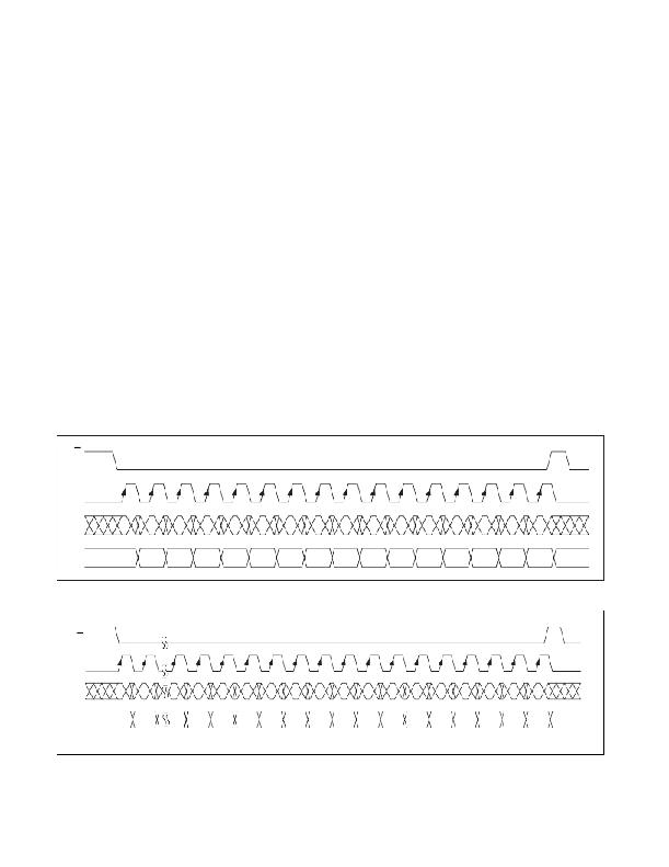
�The� MAX6966/MAX6967� are� written� to� using� the� follow-�
�ing� sequence� (� Figure� 11):�
�1)� Take� SCLK� low.�
�2)� Take� CS� low.� This� enables� the� internal� 16-bit� shift� reg-�
�ister.�
�3)� Clock� 16� bits� of� data� into� DIN,� D15� first� to� D0� last,�
�observing� the� setup� and� hold� times.� Bit� D15� is� low,�
�indicating� a� write� command.�
�4)� Take� CS� high� (either� while� SCLK� is� still� high� after�
�clocking� in� the� last� data� bit,� or� after� taking� SCLK�
�low).�
�5)� Take� SCLK� low� (if� not� already� low).�
�If� fewer� or� greater� than� 16� bits� are� clocked� into� the�
�MAX6966/MAX6967� between� taking� CS� low� and� taking�
�CS� high� again,� the� MAX6966/MAX6967� store� the� last� 16�
�bits� received,� including� the� previous� transmission(s).�
�The� general� case� is� when� n� bits� (where� n� >� 16)� are�
�transmitted� to� the� MAX6966/MAX6967.� The� last� bits�
�comprising� bits� {n-15}� to� {n},� are� retained,� and� are� par-�
�allel� loaded� into� the� 16-bit� latch� as� bits� D15� to� D0,�
�respectively� (� Figure� 12).�
�CS�
�SCLK�
�Reading� Device� Registers�
�Any� register� data� within� the� MAX6966/MAX6967� can� be�
�read� by� sending� a� logic� high� to� bit� D15.� The� sequence� is:�
�1)� Take� SCLK� low.�
�2)� Take� CS� low.� This� enables� the� internal� 16-bit� shift�
�register.�
�3)� Clock� 16� bits� of� data� into� DIN,� D15� first� to� D0� last.�
�D15� is� high,� indicating� a� read� command� and� bits�
�D14� through� D8� contain� the� address� of� the� register�
�to� read.� Bits� D7� to� D0� contain� dummy� data,� which� is�
�discarded.�
�4)� Take� CS� high� (either� while� SCLK� is� still� high� after�
�clocking� in� the� last� data� bit,� or� after� taking� SCLK�
�low).� Positions� D7� through� D0� in� the� shift� register� are�
�now� loaded� with� the� register� data� addressed� by� bits�
�D15� through� D8.�
�5)� Take� SCLK� low� (if� not� already� low).�
�6)� Issue� another� read� or� write� command,� and� examine�
�the� bit� stream� at� DOUT;� the� second� 8� bits� are� the�
�contents� of� the� register� addressed� by� bits� D14�
�through� D8� in� step� 3).�
�DIN�
�D15�
�=0�
�D14�
�D13�
�D12�
�D11�
�D10�
�D9�
�D8�
�D7�
�D6�
�D5�
�D4�
�D3�
�D2�
�D1�
�D0�
�DOUT�
�Figure� 11.� 16-Bit� Write� Transmission� to� the� MAX6966/MAX6967�
�CS�
�SCLK�
�D15� =� 0�
�DIN�
�DOUT�
�BIT�
�1�
�BIT�
�2�
�N-15�
�N-31�
�N-14�
�N-30�
�N-13�
�N-29�
�N-12�
�N-28�
�N-11�
�N-27�
�N-10�
�N-26�
�N-9�
�N-25�
�N-8�
�N-24�
�N-7�
�N-23�
�N-6�
�N-22�
�N-5�
�N-21�
�N-4�
�N-20�
�N-3�
�N-19�
�N-2�
�N-18�
�N-1�
�N-17�
�N�
�N-16�
�Figure� 12.� Transmission� of� More� than� 16� Bits� to� the� MAX6966/MAX6967�
�Maxim� Integrated�
�23�
�发布紧急采购,3分钟左右您将得到回复。
相关PDF资料
MAX6968AAE+
IC LED DRIVER LINEAR 16-SSOP
MAX6970AUE+
IC LED DRIVER LINEAR 16-TSSOP
MAX6971AUG+T
IC LED DRIVER LINEAR 24-TSSOP
MAX6974ATL+
IC LED DRIVER LINEAR 40-TQFN
MAX6977AAE+
IC LED DRIVER LINEAR 16-SSOP
MAX6978AUE+
IC LED DVR CONST-CURR 16TSSOP
MAX6979AUG+
IC LED DRIVER LINEAR 24-TSSOP
MAX6983AUG+T
IC LED DRIVER LINEAR 24-TSSOP
相关代理商/技术参数
MAX6967ATE+T
功能描述:LED显示驱动器 10-Port Constant Current LED Driver RoHS:否 制造商:Micrel 数位数量:5 片段数量: 安装风格:SMD/SMT 封装 / 箱体:PLCC-44 工作电源电压:4.75 V to 11 V 最大电源电流:10 mA 最大工作温度:+ 85 C 最小工作温度:- 40 C 封装:Tube
MAX6967ATE-T
功能描述:LED显示驱动器 10-Port Constant Current LED Driver RoHS:否 制造商:Micrel 数位数量:5 片段数量: 安装风格:SMD/SMT 封装 / 箱体:PLCC-44 工作电源电压:4.75 V to 11 V 最大电源电流:10 mA 最大工作温度:+ 85 C 最小工作温度:- 40 C 封装:Tube
MAX6968AAE
功能描述:LED显示驱动器 8-Port 5.5V Constant Current LED Driver RoHS:否 制造商:Micrel 数位数量:5 片段数量: 安装风格:SMD/SMT 封装 / 箱体:PLCC-44 工作电源电压:4.75 V to 11 V 最大电源电流:10 mA 最大工作温度:+ 85 C 最小工作温度:- 40 C 封装:Tube
MAX6968AAE+
功能描述:LED显示驱动器 8-Port 5.5V Constant Current LED Driver RoHS:否 制造商:Micrel 数位数量:5 片段数量: 安装风格:SMD/SMT 封装 / 箱体:PLCC-44 工作电源电压:4.75 V to 11 V 最大电源电流:10 mA 最大工作温度:+ 85 C 最小工作温度:- 40 C 封装:Tube
MAX6968AAE+T
功能描述:LED显示驱动器 8-Port 5.5V Constant Current LED Driver RoHS:否 制造商:Micrel 数位数量:5 片段数量: 安装风格:SMD/SMT 封装 / 箱体:PLCC-44 工作电源电压:4.75 V to 11 V 最大电源电流:10 mA 最大工作温度:+ 85 C 最小工作温度:- 40 C 封装:Tube
MAX6968AAE-T
功能描述:LED显示驱动器 8-Port 5.5V Constant Current LED Driver RoHS:否 制造商:Micrel 数位数量:5 片段数量: 安装风格:SMD/SMT 封装 / 箱体:PLCC-44 工作电源电压:4.75 V to 11 V 最大电源电流:10 mA 最大工作温度:+ 85 C 最小工作温度:- 40 C 封装:Tube
MAX6968AEE
制造商:Maxim Integrated Products 功能描述:8-PORT, 5.5V CONSTANT-CURRENT LED DRIVER - Rail/Tube
MAX6968AEE+
制造商:Maxim Integrated Products 功能描述:- Rail/Tube